Brazed Diamond Grinding Wheel Setup & Balancing for Gray Cast Iron: Installation, Debugging, and Safe Start-Up
28 03,2026
UHD
Application Tips
This UHD technical guide explains the full installation and commissioning workflow for brazed diamond grinding wheels used in gray cast iron grinding. It focuses on the most common shop-floor mistakes—dirty or mismatched flanges, uneven clamping force, skipped dynamic balancing, and improper first-run conditions—and provides corrected, repeatable procedures. The article details flange cleaning and contact checks, controlled tightening sequences, balance verification, and low-speed pre-grinding to stabilize the wheel before production. It also includes practical acceptance cues such as sound-based vibration checks and spark-color observation to assess grinding behavior. Key safety notes cover rational spindle speed selection (typically 1500–3000 rpm depending on wheel size and machine limits), correct coolant application, and trial-run precautions to reduce vibration, improve grinding efficiency, and extend wheel life in gray iron operations.
Brazed Diamond Grinding Wheel Setup for Gray Cast Iron: A Full Installation & Commissioning Workflow
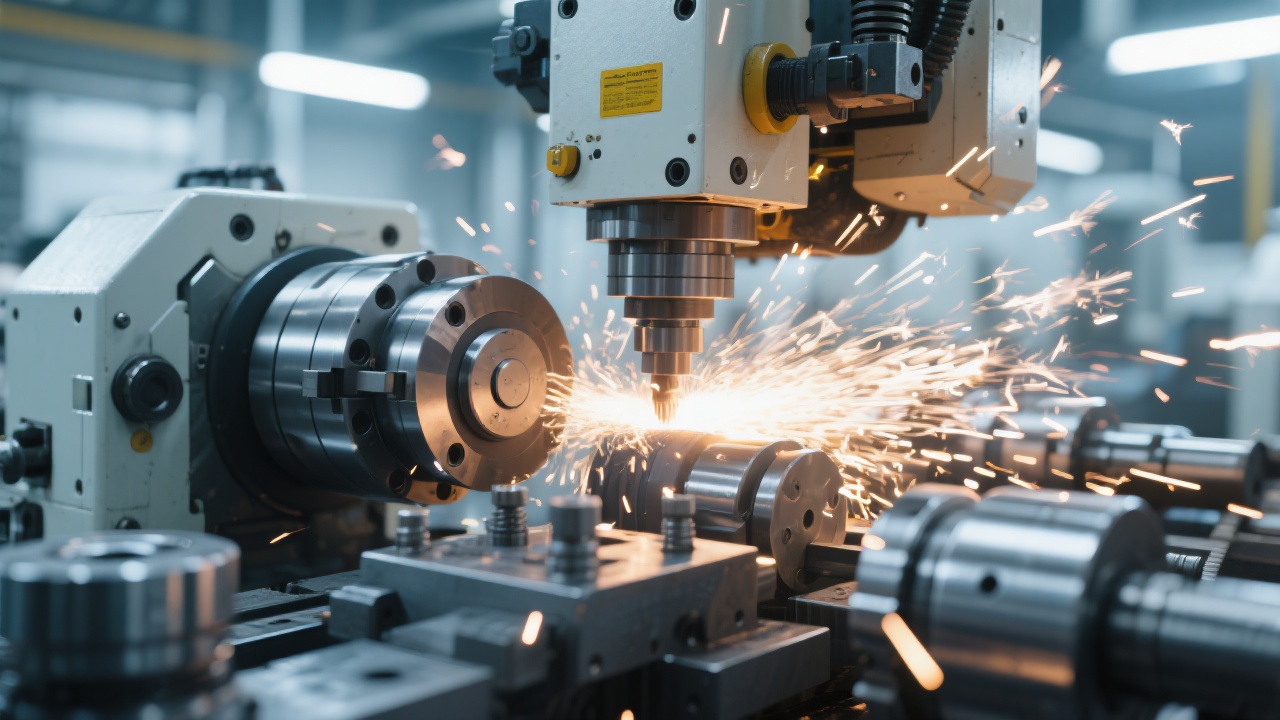
In gray cast iron grinding, a brazed diamond grinding wheel can feel “unstable” for the wrong reasons: vibration, noisy running, inconsistent sparks, premature grit pull-out, or unexpected glazing. In most workshops, those symptoms are blamed on the wheel—yet they often originate from the first 20 minutes of installation and tuning. This practical guide describes a field-proven workflow used by shop technicians and process engineers to reduce risk, improve stability, and protect wheel life—without adding unnecessary complexity.
Why gray cast iron exposes setup mistakes faster
Gray cast iron (typically 180–260 HB, with graphite flakes) fractures into powdery chips that can pack into contact zones and amplify wheel runout effects. If the flange face is dirty or clamping is uneven, the wheel may “hunt” on the spindle and create periodic loading. With brazed diamond tools—where diamond is firmly bonded to the metal matrix—mechanical stability and correct first contact are critical for predictable performance.
Installation Checklist (Before the Wheel Touches the Machine)
UHD’s application teams typically treat installation as a repeatable checklist. This reduces “invisible” defects—like trapped chips under the flange—that later show up as vibration, heat bands, or uneven spark patterns.
Tooling & measuring essentials
Dial indicator (resolution 0.001 mm recommended) for runout checks
Torque wrench or controlled tightening method for consistent clamping
Clean lint-free wipes + non-residue cleaner for flange faces
Static or dynamic balancing kit (depending on wheel diameter and machine type)
Proper PPE and dust control for cast iron grinding
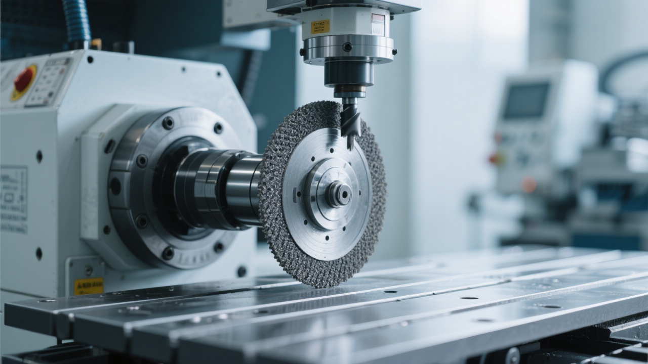
Step-by-Step Mounting: Cleanliness, Clamping, and Alignment
1) Flange and spindle face cleaning (non-negotiable)
The most frequent root cause of “mystery vibration” is not imbalance—it is contamination on the mating surfaces. Any chip, burr, rust spot, or dried coolant film can create axial tilt. The practical target is a clean, flat, dry flange face with no raised points. If there is a visible nick, it should be stoned flat rather than “tightened away.”
2) Controlled clamping force (avoid flange distortion)
Uneven or excessive tightening can distort the flange and push the wheel into lateral runout. A consistent pattern—tightening bolts in a cross sequence in small increments—generally produces better seating than a single final “pull.” For many shop environments, keeping clamping consistent between wheel changes is more important than chasing extreme torque.
Reference tolerance used in many grinding cells: aim for total indicated runout (TIR) at the wheel OD of ≤ 0.01–0.03 mm depending on wheel size and finish requirements. If TIR is larger, correct seating and flange condition before adjusting process parameters.
3) Quick runout verification before balancing
Balancing cannot “fix” a wheel that is mounted crooked. First verify spindle condition and mounting alignment with a dial indicator. If runout changes after re-clamping, it signals seating issues rather than a true balance problem.
Balancing & Commissioning: How to Prevent Chatter at 1500–3000 rpm
For gray cast iron, many shops run brazed diamond wheels in the 1500–3000 rpm band depending on diameter, machine rigidity, and required removal rate. In that window, imbalance can show up as a repeating “buzz” and a wavy contact signature on the workpiece.
Symptom
Most likely setup cause
Corrective action
Rhythmic vibration / “wobble” sound
Unbalanced wheel or distorted flange
Re-seat + balance; verify TIR first
Localized loading / dark streaks
Uneven contact from runout; insufficient coolant
Improve seating; stabilize coolant delivery
Excessive sparks / heat tint on work
Aggressive first passes; too high surface speed
Low-speed pre-grind; reduce infeed/feed
Fast grit micro-chipping at edge
Shock loading from hard entry / poor stabilization
Softer entry, steady coolant, check rigidity
A practical balancing note
Dynamic balancing is often justified when wheels are larger, when finish is sensitive, or when the spindle spends long cycles near the upper end of the rpm range. For smaller wheels or short cycles, static balancing can still deliver measurable stability—provided runout is already under control.
First Contact Matters: Low-Speed Pre-Grind and Safe Ramp-Up
The first grinding passes should be treated as a commissioning stage, not production. A controlled “pre-grind” helps the wheel seat mechanically, stabilizes coolant behavior, and reveals hidden issues (runout, resonance, poor coolant aim) before they become scrap or tool damage.
Recommended ramp strategy (reference)
Start at low rpm and light contact to confirm stability
Increase rpm stepwise within 1500–3000 rpm as the process settles
Use conservative infeed/feed for the first few passes
Listen for a steady tone (no periodic beating)
Two sensory checks technicians trust
In real shops, operators often detect instability before any gauge does:
Sound: a smooth, continuous “hiss” is generally healthier than pulsing noise.
Sparks: spark intensity and color trend can hint at heat and contact pressure changes.
Spark color: what it may indicate (shop-floor guidance)
While spark color is not a laboratory measurement, it is a useful trend indicator. For gray cast iron, a sudden shift toward brighter, more intense sparks often correlates with rising heat, sharper contact, or a parameter jump. If a stable setup suddenly produces “hotter” sparks, it is reasonable to check coolant aim/flow, infeed rate, and whether loading is beginning at the wheel face.
Coolant Use in Gray Cast Iron Grinding: Performance and Safety
Coolant is not only about temperature. In cast iron, it also influences dust control, chip evacuation, and loading behavior at the wheel/work interface. Many stability complaints are actually coolant delivery problems: wrong nozzle position, insufficient flow at the contact zone, or inconsistent pressure as filters clog.
Coolant “aim” beats coolant “volume”
A well-aimed nozzle that reaches the contact zone consistently often outperforms a high-volume stream that breaks up before it reaches the interface. A stable jet reduces re-cutting of fines and helps keep the wheel face cleaner during long runs.
Safety notes technicians should not skip
Control airborne cast iron dust (local extraction + appropriate masks/respirators).
Keep guards correctly installed; do not “open up” for visibility.
Verify wheel direction and rotation rating before ramp-up.
Stop immediately if vibration appears after rpm changes—do not “push through.”
A Practical “Do / Don’t” for Stable Gray Iron Grinding
Do
Don’t
Clean flange faces and confirm seating before tightening
Clamp harder to “solve” runout
Check TIR and address alignment first
Balance a wheel that is mounted crooked
Commission with low-speed pre-grind and gradual rpm steps
Start at full production parameters on first contact
Stabilize coolant delivery and aim at the contact zone
Assume dry grinding is “fine” without evaluating dust/heat/loading
Want the Exact Setup Sheet Used on Shop Floors?
For teams standardizing gray cast iron grinding, a one-page checklist can prevent most repeat issues: flange cleaning, clamp sequence, runout targets, balancing triggers, pre-grind ramp steps, and coolant positioning. UHD can also share real application cases comparing stable vs. unstable setups so technicians can troubleshoot faster.
Includes balancing decision tips, rpm ramp references (1500–3000 rpm), and a troubleshooting map tailored to gray cast iron.
Video clip suggestion (for training)
A short internal video showing flange cleaning, bolt tightening sequence, indicator runout check, and the first low-speed contact pass often reduces onboarding time and helps standardize operator habits across shifts.


.png?x-oss-process=image/resize,h_1000,m_lfit/format,webp)


